1 Scope
This standard specifies a method for accurately measuring the thickness of the ultra-thin silicon oxide layer on the silicon wafer surface, namely x-ray photoelectron spectroscopy (XPS). This standard is applicable to the accurate measurement of the thickness of ultra-thin silicon oxide layers prepared on the surface of silicon wafers by thermal oxidation; in general, the thickness of the silicon oxide layer applied in this standard is not more than 6 nm.
2 normative references
The clauses in the following documents have been adopted as references to this standard. For all references to the attention period, all subsequent amendments (not including errata content) or revisions do not apply to this standard. However, the parties that have reached an agreement based on this standard are encouraged to study whether the latest versions of these documents can be used. . For undated references, the latest version is applicable to this standard.
GB/T 22461 Surface Chemical Analysis Glossary (GB/T 22461--2008, ISO 18115:2001, IDT)
General principles of GB/T 19500 x-ray photoelectron spectroscopy
Surface chemical analysis of GB/T 21006 X-ray photoelectron spectrometer and Auger electron spectrometer intensity standard linearity (GB/T 21006--2007, ISO 21270:2004, IDT)
GB/T 22571 Surface chemical analysis Calibration of X-ray photoelectron spectrometer energy scale (GB/T 22571 2008, ISO 15472:2001, IDT)
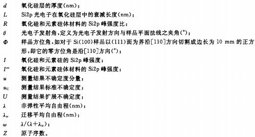
3 symbols
The following symbols apply to this standard.
4 Method Overview
4.1 Brief description
The basic principles of XPS refer to the national standard GB/T 19500. The terms established in GB/T 22461 apply to this standard.
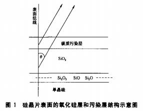
The silicon oxide layer and the carbon contamination layer on the surface of the single crystal silicon substrate are shown in FIG. 1 . Intermediate oxides exist between the silicon dioxide and elemental silicon interfaces, such as: Si2O3, SiO, and Si2O. The method needs to consider the effect of the intermediate oxide layer on the thickness measurement of the silicon oxide layer. When the surface of the sample is slightly contaminated (carbon contamination layer is 0.15-0.3 nm), the influence of the contamination layer on the thickness measurement can be neglected; when the sample surface is seriously polluted, it should be cleaned according to 6.1.2.
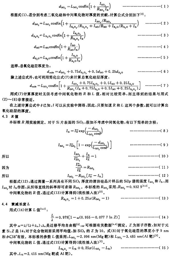
4.2 thickness calculation
The thickness of the silicon oxide layer was calculated by measuring the Si2p peak area of ​​silicon oxide and elemental silicon by the XPS method. If the intermediate oxides existing between the silicon dioxide and elemental silicon interfaces are not considered, since the Si2p photoelectron kinetic energy of silicon dioxide and elemental silicon are close to each other (a difference of about 4 eV), the relationship (1) can be obtained based on the inelastic and elastic scattering theory:
5 instruments and environmental conditions
5.1 x-ray photoelectron spectrometer
The instrument shall comply with the requirements of GB/T 19500. I shall calibrate the energy scale according to GB/T 22571; and shall calibrate the intensity scale according to GB/T 21006. The vacuum of the instrument during the test should be better than 10-7Pa.
5.2 Experimental Environment Conditions
The laboratory should avoid corrosive atmospheres, dust, vibrations, and stray magnetic fields. The laboratory temperature should be within 20 °C ± 5 °C and remain constant (± 1 °C); relative humidity should be kept less than 65%. Power supply is stable.
6 samples
6.1 sample cutting and cleaning
6.1.1 For the Si(100) sample, cut along the [110] direction, bounded by the (111) face, eg cut to a square with a side of 10 mm, its
The zero azimuth is along the I-110] direction; for the Si(111) sample, it is bounded by the (111) plane and cut along the [110] direction, eg, cut into equilateral triangles with a side length of 15 mm.
6.1.2 For the more serious pollution samples should be cleaned, the cleaning method is to immerse the sample in analytical isopropyl alcohol for about 16h, then ultrasonic cleaning, and then rinse with fresh isopropyl alcohol, and finally blowing with high-purity argon gas dry. The sample is then sent to the spectrometer for measurement or placed in a special polypropylene sample box to be sealed for testing.
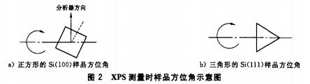
6.2 Sample Installation
All tools used to install the sample (eg stainless steel tweezers and sample holders) are cleaned using the method of 6.1.2. The operator should wear a mask and gloves. Samples were secured to the sample holder with stainless steel clips and screws. For a square Si (100) sample, the azimuth angle placed on the sample holder is 22.5° and the photoelectron emission angle measured by XPS is 34°; for a triangular Si (111) sample, the azimuthal angle placed on the sample holder is 0 °, that is, the side of the azimuth triangle is perpendicular to the sample rod axis, and the photoelectron emission angle is 25.5°. Figure 2 is a schematic diagram of the sample azimuth angle.
7 Measurement steps
7.1 XPS Measurement
7.1.1 The surface of the normal sample should be smooth and clean, free from scratches and stains, and then the sample should be mounted on the sample holder according to 6.2 and sent to the spectrograph.
7.1.2 The x-ray source is MgKa line or AIka line. The detection area should be selected at a central position more than 1mm away from the edge of the sample.
7.1.3 Use repeated narrow scans when recording Si2p spectra (scans more than 5 times).
7.1.4 Each sample is measured more than 5 times. The sample is to be taken out and reinstalled and injected at each measurement.
7.2 Data Processing
7.2.1 Subtract the photoelectron peaks generated by the x-ray satellites from the Si2p photoelectron spectrum and smooth them again.
7.2.2 Subtracting the Shirley background, the background range of the buckle is: the low binding energy of the Si2p3/2 peak of the element Si is 2.7 eV to the high binding energy of 8.2 eV, ie the binding energy is from 96.4 eV to 107.3 eV (2p3/2 of the element si). The electronic binding energy is specified as 99.1 eV).
7.2.3 Peak fitting of the Si2p spectral line is divided into 6 peaks (see Figure 3), their peak positions (binding energy values) and the element Si2p3/2. The peak distance is shown in Table 1.

7.3 Silicon oxide layer thickness calculation
The Si2p peak intensity I (peak area value) obtained by the peak fitting is used to calculate the thickness of the silicon oxide layer dioxide in the equation (2-6) or (7) in 4.1. Calculate the parameters according to 4.2 and 4.3.
7.4 Evaluation of Measurement Uncertainty
In the evaluation of the uncertainty of the measurement results, this standard aims at simplifying the process, focusing on the assessment and synthesis of important uncertainty components (the uncertainty in this standard is all relative uncertainty). According to the above principles. The uncertainty of the measurement of the thickness of the silicon oxide nano-thin layer XPS analysis on the surface of the Si wafer has four categories and six main components, as follows;

8 Measurement Report
8.1 describes the initial and final state of the measured sample.
8.2 Report experimental details of XPS measurements, such as sample azimuth and photoelectron emission angle.
8.3 Report the Si2p peak intensities of Si and Si, giving the thickness of the silicon oxide layer and the measured thickness.
8.4 lists the major components of uncertainty and gives the standard uncertainty.
8.5 Report Expanded Uncertainty.
55 LUMENS – Our long-lasting LED puck lights shine brighter with a 55 lumen, 3000K warm white glow. This LED under cabinet lighting will illuminate any area of your home. The LEDs never need to be replaced
WIRELESS REMOTE – The remote control lights include a dimmer, an optional auto off timer and on/off capabilities for convenient control of your lights. The included wireless remote will allow you to control up to 12 puck lights up to 15 feet away
SELECTABLE DIMMER - Select your desired level of brightness or press the 50% or 100% brightness button on the wireless remote
OPTIONAL AUTO OFF TIMER - Set the under cabinet lights to turn OFF with the optional timer in 15, 30, 60 or 120 minutes to converse battery life
100 HOUR RUN TIME – Each of our battery operated lights last up to 4 times longer than other puck lights on 3 AA batteries (18 included). Simply replace the batteries by twisting the light off of its base and insert new batteries
Led Puck Light,Cob Puck Light,Remote Control Light,Cordless Light Switch
Ningbo Wason Lighting Technology Co.,Ltd , https://www.wasonlight.com