3. Cutting test method
The test device used in this test is shown in Figure 1. The compressed gas produced by the compressor is sent to the cold air generating device, and the instrument and switch are adjusted to the required temperature, and then sprayed by the nozzle between the rake face of the tool and the chip. This acts as a chip evacuation and cooling cutting zone. In sub-dry cutting, the additive is dripped with the cold wind between the rake face and the chip.
In this study, continuous cutting was used as the research object. All the same materials and the same type of test were completed on the same test piece; the same material was used in the cutting stability test. Segmented continuous cutting is done to increase the comparability of similar tests.
4. Test content
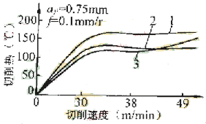
When cutting GCr12, take ap=0.75mm, f=0.1mm/r, and get Figure 2.

1. Natural cooling 2 Air cooling (-23 ° C) 3. Burning cooling
Fig. 2 Relationship between heat cut and cutting speed of three cooling methods when cutting GCr12
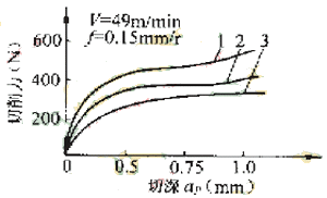
When cutting GCr12. Take V=49m/min, f=0.15mm/r, and get Figure 3.

1. Natural cooling 2 Air cooling (-23 ° C) 3. Burning cooling
Figure 3 Comparison of cutting forces for three cooling methods when cutting GC12
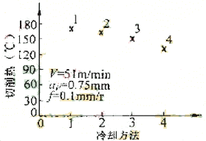
When cutting Cr12, take V=51m/min, ap=0.75mm, f=0.1mm/r, and get Figure 4.

1. Natural cooling 2. Pouring cooling 3. Air cooling (-23 ° C) 4. Sub-dry
Fig. 4 Comparison of cutting heat between different cooling methods when cutting Cr12
Previous Next
Led Fireworks Light,Voice Control Fireworks Light,Twinkle Led Fireworks Light,Led Solar Fireworks Light
Tianjin Jinji Optoelectronic Technology Co., Ltd. , https://www.jinjiled.com
