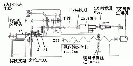
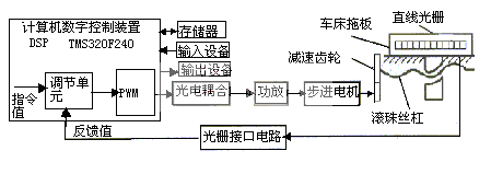
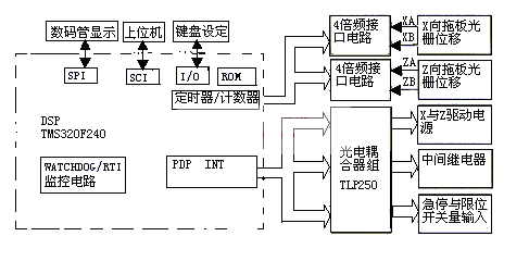
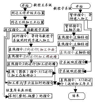
In China, economical lathes are widely used because of their low price. In the process of numerical control transformation, the single-chip system is often used. For example, the MCS-51 series single-chip microcomputer is used as the control core. The speed and accuracy of the control system are not high enough due to the performance of the CPU. The modified function is only a single CNC lathe. . In practice, the DSP TMS320F240 microprocessor is used as the control core of the numerical control system, which improves the speed, stability and accuracy of the servo system control. At the same time, it realizes the multifunctional function of the economic lathe for turning, milling and cutting. Comprehensive numerical control transformation. First, the multi-functional transformation of economical lathes Taking the modified economical lathe C616 A as an example, the lathe structure is shown in Figure 1. Figure 1 Schematic diagram of C616A lathe structure The specific method is as follows: the difference from the ordinary CNC lathe transformation is that the original lathe tool holder (or electric tool holder) is replaced with a power milling head for holding various types of shank (rod) milling cutters, and the spindle axis of the power milling head It is equal to the centerline of the lathe and perpendicular (can also be rotated 90 ° parallel to the centerline of the lathe). The force milling head is controlled by a separate motor. The power milling head is replaced by a lathe tool holder (or electric tool holder), which is the same as a normal CNC lathe. The longitudinal (Z-direction) of the lathe and the lateral (X-direction) movement of the lathe are controlled by the first set of two-axis CNC main system. In the left end of the XI axis of the C616A lathe headstock, remove the gear (Z=100) connecting the XI axis and the XII axis in the original lathe, and connect the FWl60 universal indexing head to the left end of the XI axis, and select another stepping motor (with The X-direction stepping motor has the same technical parameters, t=5mm, and the displacement control accuracy is 0.005 mm. The Y-direction stepping motor is connected with the FWl60 universal indexing head input worm. Therefore, the rotation control of the lathe spindle VI can be realized ( At this time, the lathe spindle VI is in the neutral position). The FWl60 universal indexing head and Y-direction stepper motor are mounted on a cast iron bracket. Remove the cast iron bracket and install the Z=100 gear to restore the transmission connection between the original headstock of the ordinary lathe and the feed motion. The rotary motion of the spindle is controlled by the second set of two-axis CNC subsystems. The numerical control subsystem is controlled by the signaling command of the numerical control main system. The two sets of CNC systems are preferably the same to facilitate simultaneous programming and CNC machining. The Y-direction stepping motor is directly connected to the input worm of the indexing head. The transmission ratio of the indexing head is selected to be i=1:40, and the Y-direction stepping motor is rotated by 1 revolution to drive the indexing head spindle to rotate 1/40 rpm. Rotate the stepper motor for 40 revolutions to drive the indexing spindle to rotate 1 revolution. According to the lathe spindle transmission system (see Figure 1), the indexing head spindle rotates by 1 revolution, which drives the lathe spindle to rotate 1 revolution. In the X-direction running control of the CNC lathe, the X-direction stepping motor is directly connected to the transverse ball screw. When the running length of t=5 mm is given, the ball screw rotates by 1 turn, and the X-direction stepping motor also rotates. turn. When the Y-direction running length Ly=5×40=200mm is given, the Y-direction stepping motor can be controlled to rotate 40 revolutions, that is, the lathe spindle is controlled to rotate by 1 revolution to realize the rotation control of the workpiece. In addition, from the "Machine Repair Manual", in the C616A lathe spindle drive chain, the clutch spring can be adjusted to obtain different ultimate pressure transmission cutting power. The modified C616A lathe has the functions of three-coordinate linkage and any two sets of two-coordinate linkage. Second, the transformation of the control system The core of the control system uses the DSP microprocessor-specific DSP microprocessor chip TMS320F240 from TI. With its high-performance DSP core and rich microcontroller peripheral functions, it has become an inexpensive alternative to traditional micro-control systems such as the MCS-51 and expensive multi-chip designs. It offers high-speed signal processing and digital control compared to other solutions, and provides the peripherals necessary for a single-chip solution for stepper motors and other motor control applications. 2.1 DSP TMS320F control system implementation DSP TMS320F240 is mainly composed of CPU (20MIPS high-speed computing capability), 544×16 on-chip RAM, 16K×16FLASHEEPROM, event manager, on-chip peripheral interface module (EMIF) and other parts. Unique resources with motor control are: general purpose timer, 12 PWM pulse width modulated output, 2 10-bit 8-channel A/D converters, SPI and SCI: synchronous serial peripheral interface, watchdog (WATCHDOG) and Real-time interrupt timer (RTI). Due to the high speed and high precision requirements of the CNC system, the 12-bit serial D/A converter TLV5616 is selected. The device has a flexible 4-wire serial interface, which can seamlessly connect to the F240 serial port and adopt 12-bit parallel A/D conversion. The output of the controlled object is collected and transmitted to the F240, and the F240 accurately corrects the control input in real time according to the control algorithm. Since the internal memory of the TMS320F240 cannot meet the needs, it must be expanded to expand the program memory to a 64K×16 SRAM storage part program, and the data memory is expanded to a 64K×16 FLASH ROM storage system program. The block diagram of the C616A lathe control system realized by DSP TMS320F240 is shown in Figure 2. The schematic diagram of the DSP hardware path structure of the whole lathe is shown in Figure 3. Figure 2 DSP control system block diagram Figure 3 DSP lathe control system hardware block diagram 2.2 CNC principle of turning and milling multi-function machining After the above-mentioned numerical control transformation, the numerical control main system can control the operation of the Z-direction and the X-direction movement; it can also be connected in series with the numerical control subsystem, and realize the linkage operation between the control and the Y-direction movement (the numerical control subsystem Y is controlled by the numerical control main system) Send command control to start running). The linkage processing flow control of the CNC main system and subsystem is shown in Figure 4. Third, the conclusion This method was used to transform the economical lathe C616A of our CNC center, which realized a certain CNC machining, milling, cutting and other multi-functional processing on a lathe. The main machining operations are: halved or unequal planes on shaft parts; various keyways on shaft parts; milling screws; milling grooves and cam profiles on the end faces of shaft parts; turning axes Class parts; polishing machined shaft parts. In addition, the excellent performance of the DSP system guarantees the high precision, high stability and high speed of the CNC servo system control. It has been proved that the precision of the parts processing is greatly improved, the processing range and quality of the CNC lathe are expanded, and it is very practical. Sex.
About high speed Door Accessories:
1.Driving system: High Speed Door Servo System motor and control, motor SNMA / SEJ +reducer+flang+encoder+control box
2.Other accessories: Middle aluminium bar, bottom aluminium bar, aluminium vertical track, stainless steel vertical track, brushes,round nylon strip, PVC roll, rolling steel tube complete, drum be;;s for rolling tube, side end covers, stainless steel cover, steel tubes, air bag sensor system, safety light beam, Microwave sensor 24 Gigahertz,PVC welding machine, smoke and fire sensors, PVC transparent window, magnetic loop, photocell, remote control, manual push button, sound warning alarm Led lamp traffic light
For some main accessories, here is detain introduction:
1).24G radar sensor:
Brand: Hofic
Technology: Microwave processor
Maintain time: 0.5s
Protection: IP54
Transmitting frequency: 24.125GHz
Maximum installation height: <5meter
Transmitting power density: <5mw/cm2
Power consumption: <1W(VA)
Installation angle: 0-90°(lengthways) -30-30°(crosswise)
Supply voltage: AC&DC 12V-30V
2).Photocell:
Approval CE & ISO9001
Power supply AC/DC 12-30V
Static current 25A
Action current 40mA
Mounting distance Max 10m
NO or NC contact Done by NO./NC. contact selection
Working environment temperature -42℃ to +45℃
Working environment humidity 10 to 90%RH
Appearance dimensions( controller) 123*50*32mm(L*W*H)
Appearance dimensions(Magic eye head) 19*13mm(L*D)
3). Remote control
Operating Voltage: AC220V/50HZ+-20%
Transmit power:≤100mW;Super regenerative module, strong anti-interference
Operating temperature:-30℃-+70℃
Working frequency: 433MHZ;transmitter 1527, millions of encoding chip
Accept sensitivity:≤110dB
Manipulation method: electric remote control
Configure the quantity: Wireless number; factory configuration transmitter two. Can be equipped with PT2272 digital decoder chip
Configure the function: Up, down, stop, anti-lock full-featured reproduction
4). Magnetic loop
Voltage: 12V AC/DC +-10% 24V 115V AC+-10% 230V
Power: <2VA
Continued electrical output: 7A / 250V AC
Frequency range: 20 to 200K Hz
Response time: infinity (factory setting) or adjust maintain time
Sensitivity: 0.01% to 0.1% divided into 3 levels
Protection level: IP30
Electromagnetic compatibility (EMC) Complies with EM50081-1 and EN50082-2
Detection loop inductance: the limit of 40uH to 100uH ideal value 80uH to 300uH
Operating temperature: -25 ℃ to 70 ℃
Storage temperature: -40 ℃ to 85 ℃
Relative humidity: <90% non-condensing
Temperature compensation: automatic compensation up to 50 ℃ / h
Connection type: 11 pin DIN rail socket
Dimensions: 41 * 78 * 85 mm (width * height * length)
Weight: 250 grams
5). manual push button
This exit switch button is made of ABS and has built-in indicator light make it looks more elegant and fashionbale. It can be widely used in public entrance gates, public door, home, office, hotel, etc.
Door Exit Button Push To Exit Switch Door Opener For Access Control Security
Main Feature
Fashionable appearance
Made of ABS Plastic
Easy to install and operate
Used for access control
Specification
Mechanical Life: 500,000 test
Material: Plastic
6). Limit switch encoder
Voltage: DC5V-24V
Output voltage: high voltage≥85%Vcc, low voltage≤0.5V
Maximum mechanical speed:6000rpm
Anti-vibration: 50m/s,10-200HZ,XYZeach way 2 times.
Current consumption:≤30mA
Response frequency: 0-100KHZ
Protection: waterproof,oil proof,dust prevention, IP54
The output code system: binary code
Operating life: MTBF≥30000(+25℃,2000rpm)
Rotational inertia:4.0x10⁻⁸kgm²
Maximum load:radial direction20N
Axial direction:10N
Weight: about 0.4kg
High Speed Door Accessories,High Speed Door,Electronic High Speed Door Accessories Shenzhen Hongfa Automatic Door Co., Ltd. , https://www.hfrollershutterdoor.com


Figure 4 Flow chart of linkage processing of main and sub CNC systems
Multi-functional CNC transformation of economical lathe based on DSP (Figure)
