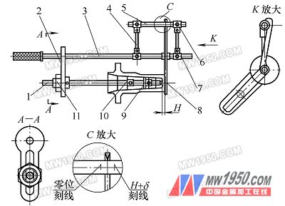
Special gauges are gauges designed to measure a workpiece and are highly targeted. Special measuring tools have the advantages of being suitable for mass production, accurate indication, simple operation and high efficiency, and their pertinence is one of their shortcomings. For the dimensions of hole diameter, hole depth, and bottom thickness involved in deep hole processing, although they can be measured by general gauges such as calipers and inner diameter gauges, there are special structures or workpieces with excessive hole depth for the inner hole, as shown in Fig. 1. The measurement of the dimensions of 40.3 mm and 172 mm in the workpiece shown creates some difficulties. figure 1 Especially for mass production, and on workpieces with special requirements for dimensional measurement, special gages are required for measurement to meet production needs. As shown in Figure 1, the workpiece is the production task undertaken by our company. The batch size is large. Due to the special requirements of the inner hole processing, in order to facilitate the measurement of the inner hole size, we have designed the special measuring tool for the bottom thickness, the special measuring tool for the hole depth and the special measuring tool for the hole diameter. It is now described as follows. Thickness gauge In the processing process, it is necessary to limit the bottom thickness (9.5 ± 2.5) mm of the blank, as shown in Figure 1, the gauge structure is shown in Figure 2. The support rod 3 is connected with the measuring rod 1 through the connecting plate 2, and the measuring rod 1 can slide in the connecting plate groove, and the position of the locking nut 11 is tightened to the fixed position after adjusting the position thereof; The sliding sleeve 7; the frame formed by the sliding sleeve 7, the arm 4 and the scale 5 can slide on the support rod 3. Its fixing can be locked by the sliding sleeve fastening screw. The gauge ruler 5 has a score line which is inscribed according to the measured size. First, the standard distance H is placed on the lower end of the measuring arm 8 and the measuring rod 1. At this time, the line is marked according to the position indicated by the measuring arm, and we call this line a zero line. Then, another reticle is engraved according to the H-size maximum value H+Δ, which is called the range upper line; the line is also drawn according to the H-Δ engraving range. Adjust the distance between the measuring rod 1 and the supporting rod 3 before use to ensure that the measuring rod can smoothly enter the workpiece hole; rotate the measuring arm 8, and observe the standard distance H between the measuring arm 8 and the lower end of the measuring rod 1 to observe whether the pointer is correct. The quasi-zero line is used to check if the gage has an error, and if so, adjust the position of the ruler so that its pointer points to zero. figure 2 1. Measuring rod 2. Connecting plate 3. Support rod 4. Arm 5. Ruler 6, 11. Lock nut 7. Sliding sleeve 8. Measuring arm 9. Positioning plate 2 10. Positioning plate Next, it can be used to measure the workpiece. The measuring rod is inserted into the hole, the measuring head contacts the bottom surface of the hole, and then the measuring arm is rotated so that the A surface contacts the outer end surface of the workpiece. According to the position of the pointer, it can be concluded that The dimensions of the workpiece between the upper and lower range lines are all acceptable. Next page 3M Measuring Tape,Waterproof Tape Measure,Stainless Steel Tape Measure,Plastic Tape Measure SHANGQIU CHAOYUE MEASURING TOOLS CO., LTD , https://www.chaoyuetools.com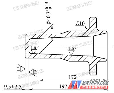
Design of special measuring tools in deep hole processing (Fig.)