User Interface Database interface Building tools Pipe joint parts information and processing technology information Previous page next page
3 3D fixture component graphics library creation
The data model is a data representation of the entity model, which indirectly reflects the interrelationships and dependencies between objective entities. The representation method has three data models: hierarchy, network, and relationship. The fixture component graphics library applies a relational model to represent its data model.
According to the above requirements for the fixture component graphics library, the fixture component library framework structure is established, as shown in Fig. 3. The framework has five parts: user interface, database, database interface, fixture component generation and library building tools. Of course, it requires a 3D software platform to run it. The functions of each part are described below. 
Figure 3 The overall framework of the fixture component library
It is the window through which the user interacts with the fixture component graphics library.
The data stored in the database are the structural parameters, materials, processing methods and other data of the fixture components. The data of various types of fixture components and related index tables are stored in the database, and the user can expand the database. Of course, another database can be created. The database is used to store the fixture components defined by the user.
The database interface is mainly used to call, query, add, delete, modify, etc. the data in the database.
It calls the template data from the database to generate a part document for the 3D solid and drives the part document with the structural parameters called from the database. The template data is equivalent to a part document of a 3D solid. In this data, in addition to defining the shape of the generated part, it is also necessary to define the part's variables, and even the relationship between the variables, which determines whether the part's shape can be properly driven by the part's variables.
Used to create new databases, including library creation, table creation, data entry, and more.
4 design examples 
Figure 4 Pipe joint processing position
This section takes the drill chuck as an example to discuss in detail the three-dimensional design process of the pipe joint fixture of the pipe joint in the MDT environment. 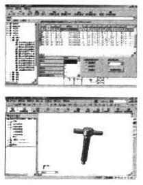
Figure 5 Call of the fixture component graphics library 
Figure 6 positioning part design 
Figure 7 Design of the clamping mechanism 
Figure 8 clip specific design
Research on Universal Fixture CAD System Based on Solid Modeling Technology (2)