A high-performance ARD2L intelligent motor protector was designed using the 32-bit processor MCF51EM256 chip of Freescale's Coldfire-V0 architecture core, and the hardware and software design of the protector was introduced in detail. Knife Gate Valve,Knife Gate,Knife Edge Gate Valve,Knife Edge Valve Haogong Valve Co Ltd , https://www.haogongvalve.com
Design and Application of Intelligent Motor Protector Based on MCF51EM256
Guo Hao 1 Li Hongjun 2 Lu Weiqing 3
(1. Guo Hao, An Kerui Electric Co., Ltd., Jiading, Shanghai 201801, China)
(2. Li Hongjun, Northern Special Energy Group, Xi'an, China) Xi'an 710025)
(3. Lu Weiqing, An Kerui Electric Co., Ltd., Jiading, Shanghai 201801, China)
Abstract: A high-performance ARD2L intelligent motor protector is designed by using the 32-bit processor MCF51EM256 chip of Freescale's Coldfire-V0 architecture core. The hardware and software design of the protector is introduced in detail. The protector integrates a number of protection functions to improve the reliability of the motor operation and reduce the economic loss caused by motor operation failure.
Keywords: intelligent motor protector, MCF51EM256, ARD2L, protection time
0 Preface
In modern industrial and mining enterprises, the proportion of motor-driven power accounts for more than 90% of the total power. They are the most important driving force and driving device in today's production activities and daily life [1, 2], for which the detection and protection of the motor is normal. Running is very important. The protector has experienced thermal relays, fuses, electromagnetic current relays, analog electronic motor protectors, and finally developed into digital electronic motor protectors, today's smart motor protectors. This paper designs an ARD2L intelligent motor protector for starting timeout, overload, underload, short circuit, phase failure, unbalance, ground/leakage, stall, blockage, external fault, etc. (hereinafter referred to as ARD2L), which can effectively improve the safety of motor operation and reduce production loss, is an ideal substitute for traditional thermal relays [3].
1 hardware design
The hardware circuit of ARD2L includes main control chip MCU, frequency signal, current signal, zero sequence current signal acquisition circuit, digital input module, relay output module, transmission output module, RS-485 communication interface, human-computer interaction unit (status indication) Light, digital tube / liquid crystal display), hardware circuit block diagram shown in Figure 1. 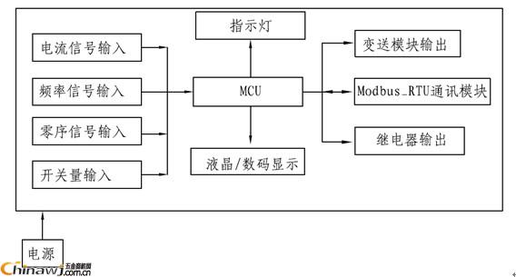
Figure 1 ARD2L hardware circuit block diagram
1.1 master chip
The MCU chip uses the 32-bit processor MCF51EM256 of Freescale's Coldfire-V0 architecture core, with a clock frequency up to 50.33MHz, built-in 256K Flash, 16K RAM, 4 independent 16-bit A/D channels, and 3 timers. 3-way SCI communication interface and built-in RTC clock, I2C, SPI, KBI interface and other resources, with a very high cost performance.
1.2 Power supply
The power supply is a key part of the equipment's normal, stable, and reliable operation. The ARD2L uses Ankerui's universal switching power supply module. The input voltage of the module is AC85V~265V, the input frequency is 45Hz~60Hz, and it has multiple isolated voltage outputs to meet the requirements of different functions for different supply voltages. Its output voltage is stable, the failure rate is small, and the output ripple [4].
1.3 signal acquisition circuit
The signal acquisition circuit is responsible for collecting current signals, frequency signals, and zero sequence current signals. Among them, the current signal is isolated by the transformer, and the AC signal is raised and sent to the CPU for software differential operation. The current sampling circuit is shown in Figure 2. Taking the A-phase 6.3A specification as an example, the current transformer ratio adopted is 100A: 20mA, 5P10 protection type. The current measurement of the scheme achieves 0.5S accuracy in the range of 1.2 times, 5S accuracy in the range of 8 times, and the overload capacity is calculated by 8 times, that is, the current is added to the transformer by 50.4A, and the current through the sampling resistor R1 is 10.08. mA, the voltage across the terminal is 0.886V. At the same time, the sampling signal is raised to a voltage of UREF=1.2V, so that the amplitude of the AC signal is greater than zero, which is convenient for A/D sampling; a voltage limiting diode is added at the output end of the circuit to limit the input voltage to 3.3V or less, which can be used for A. The /D sampling channel provides excellent protection. 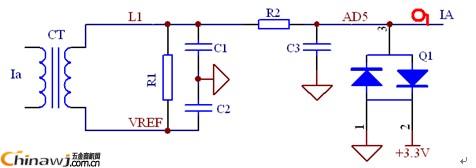
Figure 2 current sampling circuit diagram
The frequency sampling circuit is shown in Figure 3. The circuit uses the MCP6002 dual op amp for two-stage amplification, with a small primary amplification factor and filtering between the primary and secondary. The secondary op amp shapes the AC signal into a square wave signal, captured by edge triggering, and then The measurement frequency is calculated inside the CPU. 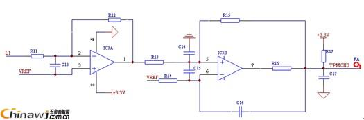
Figure 3 frequency sampling circuit diagram
1.4 human-computer interaction interface
The display of the human-computer interaction interface adopts a digital tube or a liquid crystal. The user can select the display mode according to actual needs, and the input adopts a button mode. Among them, the digital tube display adopts dynamic scanning mode, and its driving circuit is composed of 74HC595 and triode; the liquid crystal display adopts 128 dot matrix Chinese liquid crystal of Tuopuwei LM12832BCW, and its data transmission adopts SPI serial port, which can greatly save CPU resources. At the same time, the LED and LCD display are controlled by the same SPI interface, making the two display modes universal.
1.5 Control Module
The control module is mainly composed of digital input and output, as shown in Figure 4. Among them, the switch input is used to monitor the switch state of the circuit breaker and contactor and the industrial interlock state of the collection site. It can also be used for the start and stop control of the motor according to customer requirements. The switch output is mainly used to output the trip signal and alarm. Signal and remote start/stop signals. 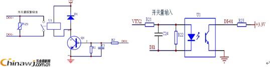
Figure 4 digital input and output circuit
1.6 Communication / Transmitter Module
The communication module adopts RS-485 module Modbus RTU communication protocol, which can realize functions such as telemetry, remote control and remote signaling. The transmission is to convert the current signal we need into DC 4~20mA analog output, which is convenient to form a network system with PLC, PC and other control machines to realize remote monitoring of motor operation.
2 software design
The software design of ARD2L mainly adopts embedded C language. The protection software design includes initialization of power-on system configuration every time, key register reset, judge whether the display unit is digital or liquid crystal, relay initial state, A/D sampling initialization and Calculation and protection of electrical parameters. The main function of the software is as follows:
Void main(void)
{
DisableInterrupts;
MCU_initi(); //CPU initialization
If(_RES==0) //Just judge that it is digital tube or LCD
Led_or_lcd=0;
Else
{
Led_or_lcd=1;
PTBDD_PTBDD2=1;
PTDDD_PTDDD4=1;
Lcd_init2();
}
recover_FIRSTFLAG (); / / restore memory calibration data
If(FIRSTFLAG!=0x1234){init_flash();}
Else recover_byte();
Initi_uart2();
Relay_all_initi(); //Relay in place initial state
EnableInterrupts //Start interrupt
Vref_init();
Sampling_init(); //AD sampling initialization
For(;;)
{
__RESET_WATCHDOG();
If(over_flag==1) //calculate and protect
{
Over_flag=0;
measure_ABC();
Protect();
Sent(); // send output
}
Measure_frequency_a(); // frequency measurement
Rtc_time_deal();
Warning_deal();
Trouble_deal();
Program1(); // Relay programmable processing
Event_deal();
Getkey();
DI_read();
Reset(); // reset
Lamp_deal();
Stat(); // statistics total running time, parking time
Display(); // measurement data and protection event display
}
}
The software flow of ARD2L mainly includes A/D signal acquisition program, TPM frequency measurement program, electrical parameter calculation program, protection processing program, various communication protocol processing programs, etc. Some program flow is shown in Figure 5. 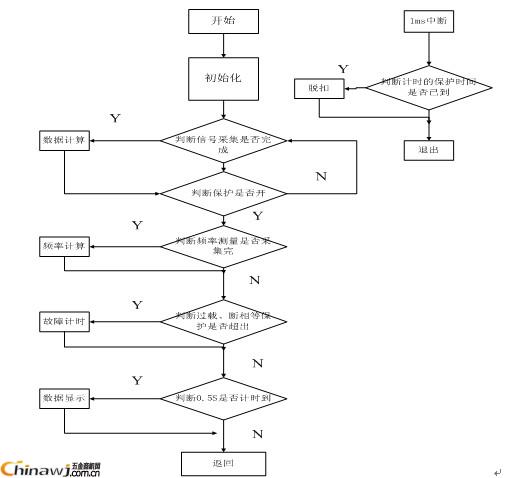
Figure 5 main program flow chart (part)
3 test results and accuracy verification
3.1 Current accuracy test results
The current accuracy test source uses Nanjing Dandike's DK-34B1 AC sampling transmitter, in which the fundamental wave test is performed by adding the third harmonic of 40% distortion rate. Table 1 tests the RMS value and fundamental value of the three-phase current of 8.3A ARD2L intelligent motor protector. It can be seen from the data in the table that the accuracy of the ARD2L intelligent motor protector in the measurement range of 10%~120%Ie is satisfied. Class 0.5, Ie is the rated power of the motor [5].
Table 1 ARD2L intelligent motor protector three-phase current test results
index
standard value
6.3A specification
Phase A
Phase B
Phase C
Valid value
Fundamental wave
Valid value
Fundamental wave
Valid value
Fundamental wave
Current
0.63
0.62
0.59
0.64
0.59
0.62
0.58
6.3
6.29
5.91
6.31
5.92
6.29
5.89
7.56
7.54
7.05
7.55
7.06
7.54
7.03
3.2 Protection time test results
ARD2L intelligent motor protector has protection functions such as start timeout, overload, underload, short circuit, phase failure, unbalance, ground/leakage, stall, blockage, external fault, etc., and protection time test according to JB/T 10736-2007 standard See Table 2.
Table 2 ARD2L protection time test results
Start timeout:
Trip delay (S)
0.1
10.0
999.9
the first time
0.110
9.950
993.882
the second time
0.117
9.965
993.859
the third time
0.119
9.961
993.872
Blocking protection: tripping field value (250%)
Trip delay (S)
0.1
5.0
600.0
the first time
0.122
5.031
596.455
the second time
0.128
5.037
596.458
the third time
0.134
5.043
596.431
Underload protection: trip domain value (50%)
Trip delay (S)
0.1
5.0
600.0
the first time
0.130
5.012
596.401
the second time
0.134
4.996
5.96.393
the third time
0.129
5.015
596.349
Unbalance protection: trip domain value (30%)
Trip delay (S)
0.1
5.0
600.0
the first time
0.126
5.003
596.400
the second time
0.131
5.009
596.362
the third time
0.121
5.007
596.354
Ground/Leakage Protection: Tripping Field Value (80% or 30mA)
Trip delay (S)
0.1
0.5
600.0
the first time
0.117
0.519
596.444
the second time
0.124
0.528
596.432
the third time
0.135
0.517
596.416
Short circuit protection: tripping field value (500%)
Trip delay (S)
0.1
10.0
600.0
the first time
0.135
9.973
596.564
the second time
0.133
9.969
596.472
the third time
0.136
9.967
596.526
Phase failure protection:
Trip delay (S)
0.1
1.0
600.0
the first time
0.124
1.036
596.456
the second time
0.138
1.033
596.382
the third time
0.132
1.035
596.179
External fault:
Trip delay (S)
0.1
5.0
600.0
the first time
0.126
4.976
595.711
the second time
0.112
4.989
595.801
the third time
0.124
4.988
595.836
It can be seen from Table 2 that the protector meets the accuracy requirement of the trip delay protection time error of ±10% or 100mS [6].
4 Typical applications
The ARD2L intelligent motor protector wiring in direct start mode is shown in Figure 6. Among them, the start and stop of the motor is controlled by the on-site button (the protector itself does not control the start and stop of the motor), and the attracting coil of the contactor KM is serially connected to the normally closed contact of the trip relay. After the power is turned on, when the start button SF is pressed, the KM attracts the coil to be energized, so that the KM main contact is closed and the motor starts to work; when the parking button SS is pressed, the KM attracts the coil to lose power, the KM main contact is released, and the motor stops working. . The remote start must be controlled by the host computer, and the protector itself is not controlled. 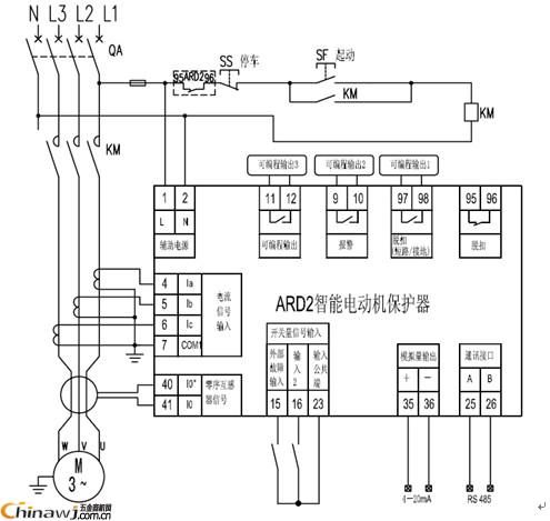
Figure 6 ARD2L motor protector direct start mode wiring diagram
5 Conclusion
This paper uses EM256 to design a high performance and multi-function ARD2L intelligent motor protector, and introduces its hardware circuit such as power supply, signal acquisition, input and output control, etc., and analyzes the protector operation through software main function and flow chart. process. Test results of current accuracy and protection time show that the protector has excellent measurement and protection functions.
Article source: "Electrical Technology", 2014, issue 3
references:
[1] Ma Xinjun, Motor Protector Design, Master's Thesis, Northeastern University, 2005.
[2] Ding Jinlei, ARM-based motor integrated protector device design, master's thesis, 2008.
[3] Ankerui Electric Co., Ltd., ARD2 Intelligent Motor Protector Selection Manual, 2013.
[4] Ren Zhicheng, Zhou Zhong, Principles and Application Guides for Digital Meters for Power Measurement, China Electric Power Press, 2007.
[5] ARD3 Series Intelligent Motor Protector, Shanghai Enterprise Standard, Q/TDEI 27-2011
[6] JB/T 10736-2007 Low voltage motor protector.
Http://news.chinawj.com.cn Editor: (Hardware Business Network Information Center) http://news.chinawj.com.cn
Design and Application of Intelligent Motor Protector Based on MCF51EM256